 Arabic
 Chinese
 French
 German
 Hebrew
 Italian
 Japanese
 Portuguese
 Spanish
3D Mapping Projector
Use this display type to wrap images around a three-dimensional object, such as a car or a sofa, by projecting onto the surface of the physical object.
See under “2D Display/Projector” for details on most fields in this dialog box.

Lens Shift
Many projectors can project their image off-axis. For example, most office grade projectors have a fixed shift that allows the projector to be placed horizontally on a desk, and yet project an image on a wall where the bottom of the image is at or above the desk’s level. Some professional grade projectors have adjustable lens shift – sometimes in both the vertical and horizontal directions.
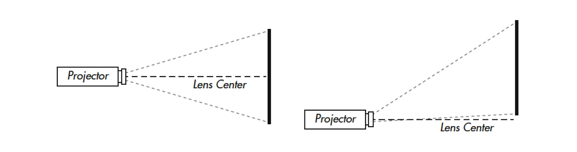
When mapping images onto a three-dimensional object, it is important to account for the lens shift in order to obtain a correct mapping. The lens shift is described as a percentage of the total image height and width. Hence, for a vertical lens shift upwards from the projector’s center (as shown in the illustration to the right above), you specify a positive shift value. If the image is shifted so that its bottom coincides with the projector’s center line, it is said to be 50%. That is, the image is shifted upwards by 50% of its total height.
The same applies in the horizontal direction, where a positive percentage value shifts the image to the right and negative to the left.
NOTE: Some projector manufacturers refer to a shift of half the image height as “100%”. Furthermore, the lens shift stated by the projector manufacturer is often an approximation. You’re advised to make your own assessment of this value rather than relying on the manufacturer’s stated lens shift. Entering an incorrect value may impede your ability to use WATCHOUT’s calibration feature to align the projector.
The lens shift can either be determined and entered manually, or it may be derived as part of the projector calibration (see “Calibrate”). In general, it is best to measure the lens shift ahead of time, and enter it manually. That works well for projectors with a fixed lens shift, but may sometimes be harder when using variable lens shift in an installation.
Lock Lens Shift During Calibration. Select this option if you’ve determined the lens shift accurately ahead of time. This stops WATCHOUT from attempting to calculate these parameters, which may simplify the calibration procedure.
Position
This tab in the dialog box specifies the location, target point, rotation and focal length of the projector. While the values may be edited numerically, you typically use the “Calibrate” tab instead to determine all these values automatically.
Position/Point At
Specifies the position and target position of the projector, in 3D space. The target position of a selected projector is indicated by a yellow point at the end of the projection beam in the Stage window. To change the position interactively, drag the projector in the Stage window. Likewise, to change the target position, drag the yellow point in the Stage window.
To orient the projector in 3D space, use the “View” commands on the Stage menu to rotate the Stage window in order to look from the top or from the side. Alternatively, use the “View” tab in this dialog box to move the projector while viewing the scene from the projector.
Rotation Around Optical Axis
Rotates the projector, allowing you to use the optimal angle to cover the projection object.
CAUTION: Some projectors have restrictions on how they may be mounted or rotated, due to air-flow and heat reasons. Always check the documentation before using a projector in any other orientation than horizontally.
Width / Distance Ratio
The focal length of the projector’s lens, expressed as the ratio between the image width and projection distance. A small value here indicates a wide angle lens, while a larger value indicates a long throw lens.
Lock Zoom During Calibration
Checking this option will improve end-results if you are projecting onto objects that will vary in their distance from the projector. In order to get optimal results, the width / distance ratio (zoom) must be known from the projector specification.
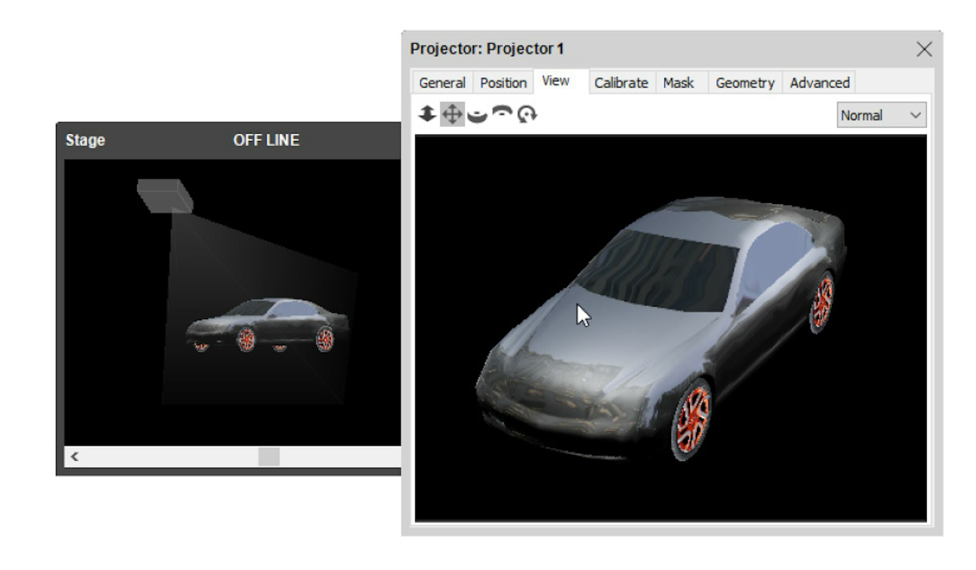
View
The View tab in the 3D Mapping Projector’s dialog box shows the scene from the projector’s viewpoint, as if looking through a camera’s viewfinder. This has two important advantages:
- It allows you to position the projector interactively, using the controls along the top of the dialog box, which is often more intuitive than dragging the projector and its target point in the Stage window.
- It shows you the scene from the projector’s viewpoint, allowing you to visualize the scene from any vantage point – not just the front, top and left views available in the Stage window.
As you adjust the view position using the controls along the top of the dialog box, the Stage window shows the effect this has on the projector. Moving the projector in this way also updates the numeric values in the Position tab accordingly.
HINT: You can select a control and then drag in the view area, or simply drag the control. Press the initial letter on the keyboard to switch among the controls.
The menu in the top right corner controls the behavior of the physical projector connected to the display computer, with the following options:
Normal. Project the image displayed in the View tab.
Muted. Project nothing (black). Useful when calibrating a projector, in which case you may want to mute other projectors.
White. Project all white. Useful to see the coverage of the projector, to make sure it covers the mapping object.
White Masked. Project white, but include any masks defined on the Mask tab.
Pattern. Project a distinct pattern, which is useful when focusing the projector.
Calibrate
The Calibrate tab shows the same image as the View tab, but allows you to attach and adjust calibration points to the projector and the real-world projection object. This semi-automatic calibration method allows WATCHOUT to calculate all the settings on the Position tab (as well as, optionally, the lens shift values). This is useful when mapping images onto a physical, three-dimensional object.

To use this method, you must:
- Have a physical object to map images onto.
- Have a 3D model that accurately matches the physical object.
- Display the 3D model using a Cue on a timeline.
- Place the physical projector so it illuminates the object as desired.
- Use the View tab to position the projector inside WATCHOUT in roughly the same way.
Once that’s done, select “Edit Points” on the Calibrate tab and start adding points. To add a point, you click somewhere inside the 3D model, as shown above. To add a point close to an edge, press the mouse down inside the model, then drag it towards the edge. Points can not be placed outside the model. You can add any number of points, but need to have at least six points. Calibration points should be placed at easily recognized positions on the model allowing you to accurately correlate the point in the Calibrate tab with the corresponding point on the physical object. Remove a point by selecting it and choosing Clear on the Edit menu.
HINT: Enlarge the dialog box to position points more accurately.
To calibrate the projector’s position, do as follows:
- Select “Line Up Points”.
- Grab and move one of the calibration points while looking at where it will be projected on the physical model.
- Move the point until it hits the same spot on the physical model.
- Do this for all calibration points until the image maps properly onto the model.
HINT: Use the tab key to switch between the “Edit Points” and “Line Up Points” modes, and arrow keys for precise positioning.
As you work your way through aligning the points onto the physical object, the color of the calibration lines may vary.
Yellow. The positioning of points on the model makes sense to WATCHOUT, allowing it to calibrate the projector’s position accordingly (you’ll also see the projector move in the Stage window, and the projected image move on the physical object).
Red. The position of some points doesn’t make sense, and can not be used to calculate the projector’s position.
Sometimes it may be hard to position the calibration points to avoid the red indicator lines. It’s sufficient to have a single point off for this to happen. This can also be caused by incorrect Lens Shift values. If you’re unsure about the actual lens shift, it’s sometimes better to uncheck “Lock Lens Shift During Calibration,” allowing WATCHOUT to calculate this as well.
NOTE: The 3D object must be stationary in the Stage window for this calibration to work. If you move the image in the Stage window, you need to start over with the calibration.
This video shows how the calibration feature is used:
https://www.dataton.com/3d-projection-mapping-basics
See common sections, later in this chapter, for the remaining tabs and fields in this dialog box.