 Arabic
 Chinese
 French
 German
 Hebrew
 Italian
 Japanese
 Portuguese
 Spanish
Inputs
Inputs receive signals from the outside world. Those signals can then be used to control and influence the behavior of WATCHOUT by starting and stopping timelines and by controlling various cue parameters.
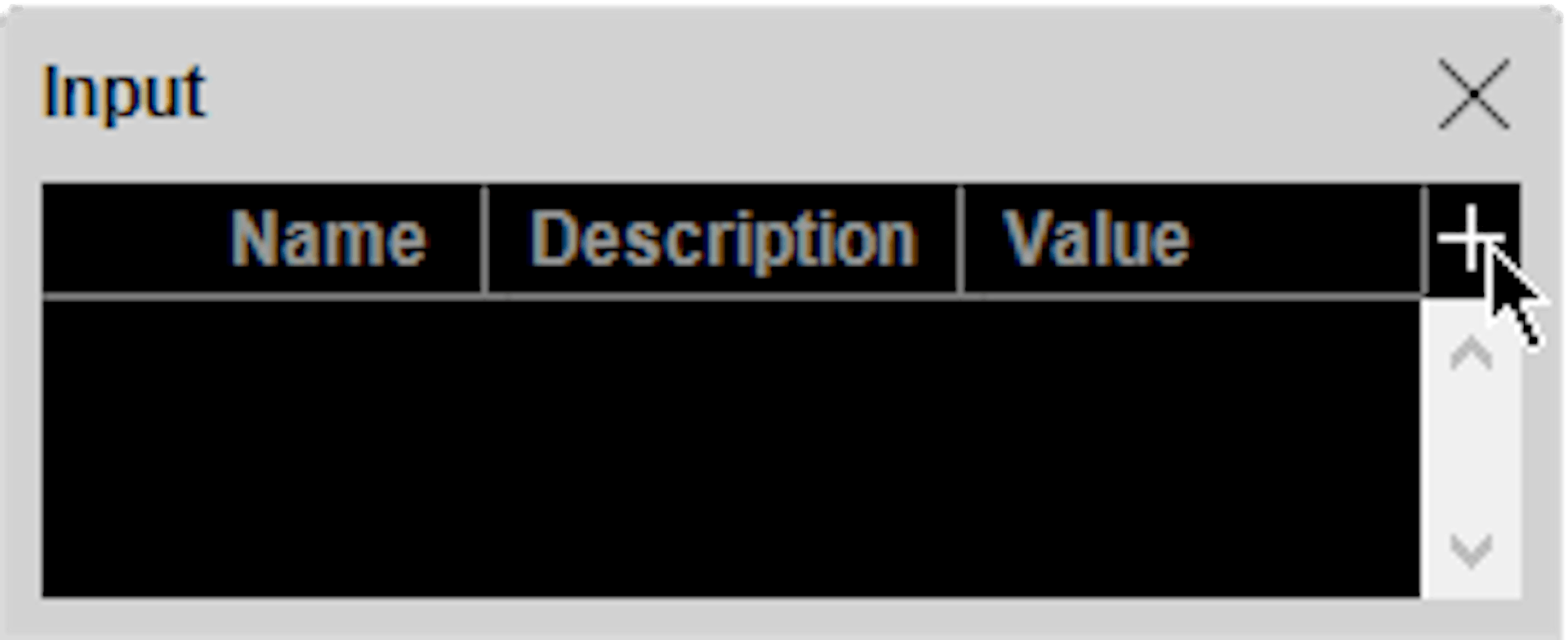
To create an input, first open the Input window using the Window menu, then choose “Add...” from the pop-up menu located in the upper right corner of the Input window. Depending on the type of input chosen, this displays a dialog box allowing you to enter its specifications. See the following sections for details on the various kinds of inputs.
NOTE: When you are using the production computer, inputs are managed there. When not using a production computer, inputs are managed by the primary display computer in the cluster.
Generic Input
Use a generic Input when you want to control its value using the WATCHOUT control protocol. The default range of a generic input is 0 through 1, although you may set the upper limit to any positive value using the Limit field in the Generic Input’s dialog box. To control a generic input, use the setInput command.
Connecting a MIDI Device
Connect your MIDI device to a USB port (or other suitable MIDI interface) on your WATCHOUT computer. Many newer devices come with a direct USB connection. Older MIDI devices often use a standard 5-pin DIN connector, in which case you need a MIDI-to-USB adaptor, as shown on the right, or other Windows-compatible
MIDI interface. If you have multiple devices with MIDI capabilities connected to your system, you can choose which one to use for MIDI input in the Control tab of the Preferences dialog.
NOTE: Most MIDI devices that connect using USB occupy an entire MIDI bus on their own. Since WATCHOUT handles only a single MIDI bus, you won’t be able to combine such a device with other MIDI devices. When connecting multiple MIDI devices through the same bus, WAT CHOUT can handle up to 16 devices simultaneously.
IMPORTANT: When using the production software, connect your MIDI interface to the production computer. Otherwise, connect it to the primary display computer. Turn on and connect your MIDI interface and devices to your computer before starting WATCHOUT.
MIDI Controller Input
A MIDI Controller Input brings in a knob or slider from a keyboard, or similar signal from a MIDI-compatible device or software. This type of MIDI data is sometimes referred to as a “Continuous Controller”, “Control Change” or “CC” message.

Enter the MIDI channel number and controller number to use, if you know them. If not, click “Learn” and move the controller.
NOTE: The controller number used in the MIDI protocol is often not the same as any number next to the knob on the device. Furthermore, many devices have programmable controllers, so the actual controller number may vary depending on the device’s configuration.
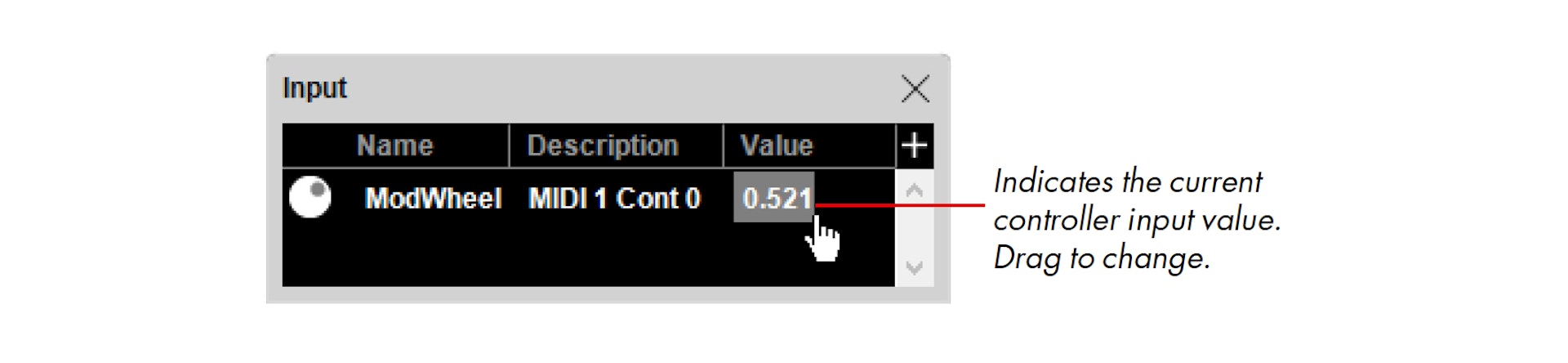
Do not select “Resolution: High” unless you know for a fact that the controller transmits high resolution data. Regardless of the resolution being used, WATCHOUT normalizes all controller inputs to a number in the range 0 through 1, as indicated in the Input window’s Value column.
Circular interpolation should be set if using external controls able to rotate more than 360 degrees (e.g. an Endless Wheel Encoder, Jog-wheel or Jog-dial). This makes the input value interpolate the shortest distance between two points on a circular basis. This to avoid a jump backwards, if for example a rotational animation exceeding one revolution is applied on an object, which would be the case if using linear interpolation.
When done, click OK in the MIDI Controller dialog box. Verify proper operation of the input by moving the controller and observing the bar graph in the Input window.
MIDI Note Input
A MIDI Note Input brings in MIDI keyboard messages, often referred to as “Note On/Note Off” messages.
When you’ve entered all the information, click OK in the MIDI Note dialog box. Verify proper operation of the input by pressing the key and observing the bar graph in the Input window. If the keyboard has velocity sensitivity, the velocity is indicated by the magnitude of the value.

DMX-512 Input
A DMX-512 Input brings in the value of a DMX channel. DMX-512 is a protocol used by most lighting consoles, dimmers, moving lights and other similar devices.
WATCHOUT uses the computer network to receive DMX data with the Artnet protocol. Many lighting consoles can send Artnet over an Ethernet network. Otherwise, a DMX-to-Ethernet adapter must be used. In either case, you need to know the DMX channel number(s) to be used for WATCHOUT, as well as the Artnet Universe number used to send those channels. Set the default ArtNet Universe from which WATCHOUT will receive data under the Control tab in the Preferences dialog box. As the Universe can be set per output, the default setting can be ignored if multiple Universes are to be used.
Add a “DMX-512 Input” to the Input window using the plus button in its top, right corner. Specify the desired DMX channel number.
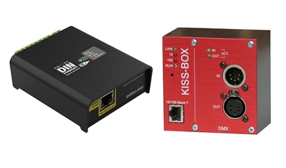
DMX-to-Ethernet adapters from Enttec and Kissbox
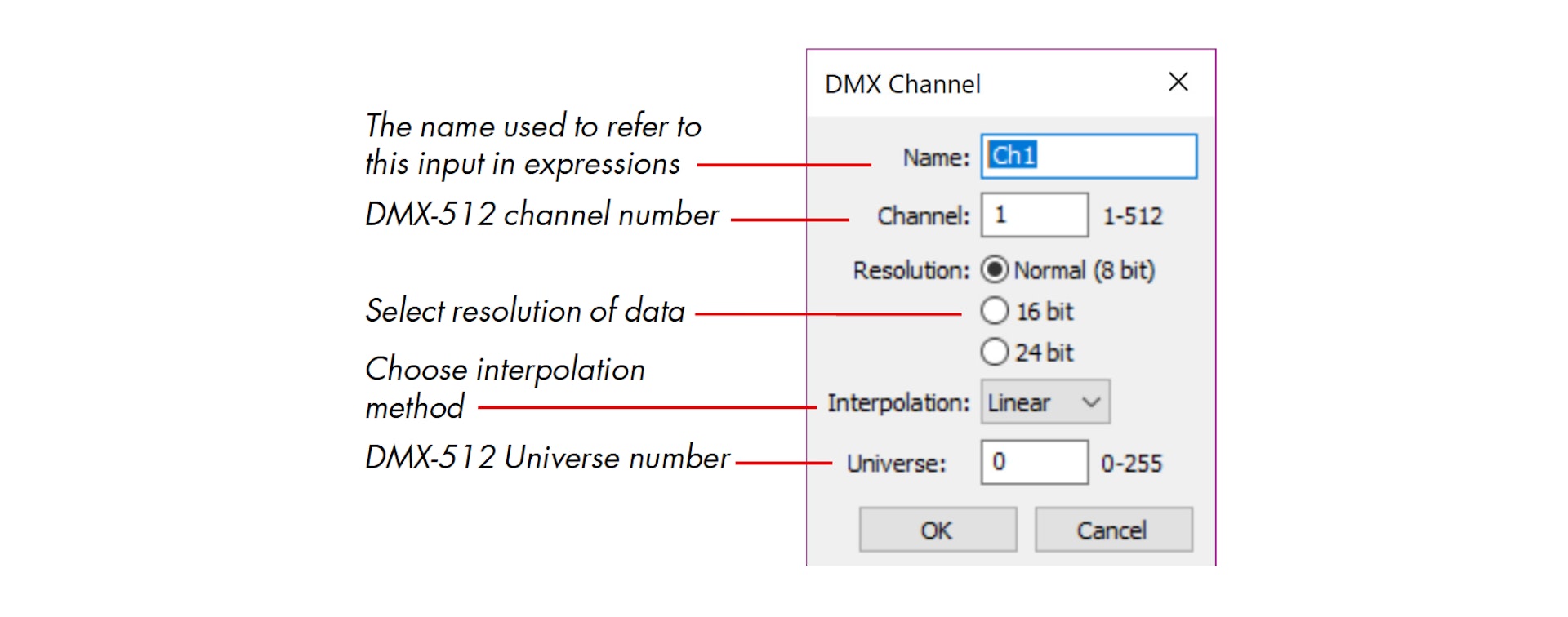
Choose the appropriate interpolation method (see explanation under the section on “MIDI Controller Input”, click OK in the DMX Channel dialog box and verify proper operation of the input by moving the fader for the specified channel and observing the bar graph in the Input window. WATCHOUT normalizes DMX values to a number in the range 0 through 1, as indicated in the Input window’s Value column.
Learn more about Artnet here:
https://en.wikipedia.org/wiki/... style="color: rgb(127,127,127)">Resolution. Some lighting consoles support higher resolution values (16 or 24 bit). Such values are generally required to control, for example, the position of images in WATCHOUT, since the standard 8 bit DMX resolution (0...255) is too low for this purpose. If your console is capable of outputting 16-bit or 24-bit DMX values, choose the appropriate resolution in the DMX input settings and enter the base (coarse) channel number. WATCHOUT will derive the coarse 8 bits from this channel and the fine bits from the following one or two channels.
Tracking Input
A Tracking Input is a multi-variable type of input that brings in positional and rotational data from a live motion tracking system into WATCHOUT.
Any tracking system that supports the RTTrPM protocol may be used, and the information sent by the system can either control the position and rotation of a media cue or act as a trigger for tasks.
Enter a name and a trackable ID to start using a Tracking Input.
The name is used inside of WAT CHOUT to refer to this input in expressions and in media cues that should be controlled by the tracking input. The trackable ID is determined by the tracking system that is being used. For details on how to determine the trackable ID value, please refer to the manual of the tracking system being used.
The six checkboxes allow you to select which type of data will be applied to media cues controlled by the tracking input. If a type is deselected, and thus no longer processed, it will not be applied to media cues. For example, deselecting X under Position means media cues will no longer be affected by translation on the X-axis received from the tracking system.
To use the different components in a tracking input in expressions or triggers, specify them as: <Tracking Name>.<component> where component may be X, Y, Z, Roll, Pitch, or Yaw. To use the “Roll” component of a Tracking Input called “MyTrackable“ in an expression you would write the following: MyTrackable.Roll
During periods of high network traffic or system load, the tracking of an object may seem to “fall behind”. In these scenarios, tracking results may be improved by selecting “Use Prediction”. This is especially useful when the tracked object(s) moves in a predictable way, e.g. at a constant speed.
The “ms” (millisecond) setting controls the magnitude of prediction. It should be set according to the lag in the complete system.
NOTE: Using prediction when the tracked object may quickly change its direction or speed can cause an “overshoot” in its position or rotation.
Controlling Tween Tracks
Inputs can be used to control parameters of cues, similar to the way tween tracks are used. This provides external control over most parameters. To use this capability, add the desired type of tween track to the cue, then click the formula button located in the header area of the tween track. You may need to click the triangle in the tween track header to reveal the formula button. Some tween tracks have multiple controllable parameters.

Clicking the formula button brings up a dialog box allowing you to enter the control formula. By default, the formula consists only of the TweenValue item.
NOTE: In order to access the formula of some tween tracks, such as Position, Scale and Rotation, you must first enable this in the cue’s settings (see “External Control of Position, Rotation and Scale”). For still images, you must also select “More Effects and Capabilities” in the image’s specification (see “Optimize For”).
Some tween tracks, such as Position, contain multiple values, one for each dimension controlled by the tween track (such as X, Y and Z position).
The TweenValue identifier represents the tween track itself. To control the parameter using an input, simply enter the name of the input instead, as shown in the illustration below, or enter a formula combining inputs, numerical constants, operators and the original TweenValue (see “Expression”).

Triggering Tasks
You can use an input to start an auxiliary timeline by entering the name of the input in the Trigger column of the Task window.
Press Enter to complete the formula. The task will be started whenever the value of the formula entered in the Trigger column becomes non-zero. You can create more elaborate starting conditions by entering a more complex formula including multiple inputs, numeric constants and operators (see “Expression”).
IMPORTANT : Most media cues need some time to prepare before they will appear properly on stage. Therefore, it is generally not a good idea to put such cues at the very beginning of an auxiliary timeline. Leave about a second or so empty at the beginning of the timeline.
HINT: You can only use a trigger to start a task – not to stop it. To stop a task, use another task with a timeline containing a Control Cue that targets the timeline to be stopped. Trigger this second task using the desired condition.
