 Arabic
 Chinese
 French
 German
 Hebrew
 Italian
 Japanese
 Portuguese
 Spanish
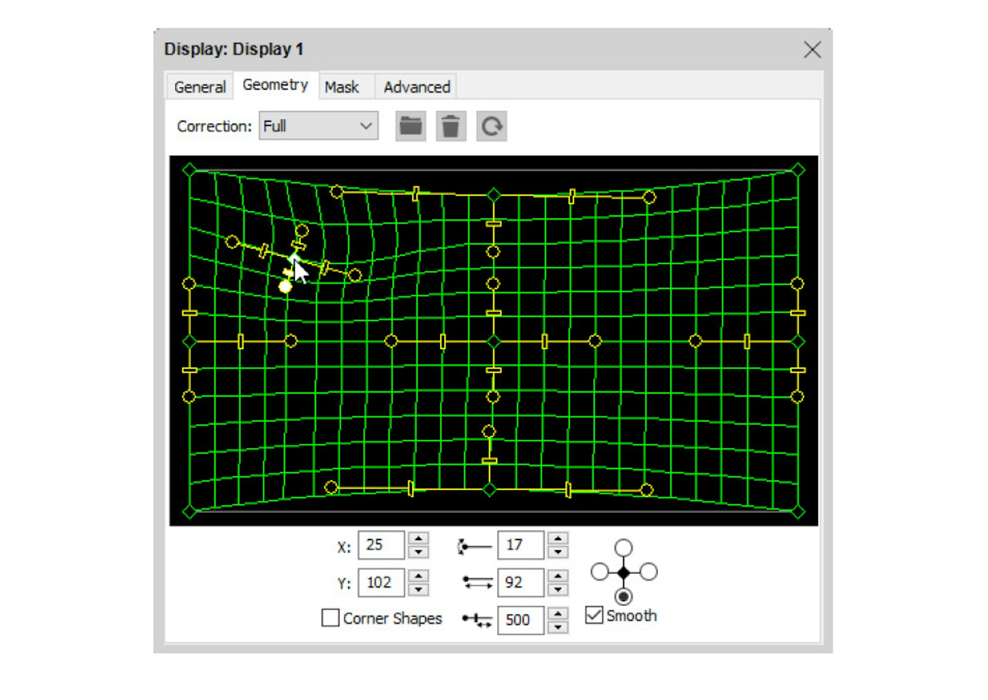
Geometry Correction
These settings allow you to compensate for any errors caused by projection off-axis (perspective), on a slightly curved surface or to account for any optical distortion.
NOTE: Projecting straight from the front onto a flat surface always gives the best image quality. Use geometry correction only when necessary.

Select the type of correction to be performed using the “Correction” menu, which has the following options:
None. No geometry correction.
Perspective. Provides perspective control, for use when projecting off-axis onto a flat screen.
Horizontal. Compensate for the screen curvature when projecting onto a horizontally curved screen.
Vertical. Compensate for the screen curvature when projecting onto a vertically curved screen.
Full. Maximum flexibility, for use when projecting onto spherically curved screen or other uneven topologies.

The numeric fields at the bottom of the dialog box show values corresponding to the currently selected correction mode, point and handle. The buttons next to each numeric field adjust the value with single pixel accuracy.
Corner Shapes. Adds bezier handles to the corners, allowing you to compensate for minor optical distortion, often associated with wide-angle lenses.
Smooth. Avoids abrupt kinks in points by keeping all tangents straight. Uncheck to allow opposing handles to move independently of each other.
HINT: Your display computers need to be online to see the changes live on screen as you make them.
Perspective Correction
To compensate for the keystone-shaped image caused by off-axis projection, choose Perspective on the Correction pop-up menu and drag the corners of the grid until the image appears rectangular on screen.
HINT: You can use the Copy and Paste commands on the Edit menu to transfer the geometry settings to other displays.

Horizontal or Vertical Correction
Adds bezier handles to the top/bottom or left/right sides, allowing you to compensate for projection on a curved surface.

Adding Correction Points
In Full correction mode, you can add control points to the grid by Control-clicking the desired location. This can be used to handle geometry adjustments when projecting on asymmetric or uneven surfaces.
HINT: Use the Copy and Paste commands on the Edit menu to transfer the geometry settings to other displays.
HINT: Correction points can be adjusted using the keyboard arrow keys.
In some cases, when projecting onto complex geometry, you may be better off with a proper 3D model of the geometry, and then using the 3D mapping capabilities of WATCHOUT instead of trying to fit the image using geomoetry correction.
It may occasionally be advantageous to combine the two techniques. In general, you shouldn’t need to use geometry correction for a “3D Mapping projector”, assuming that the 3D model you have is an accurate representation of the object upon which you are projecting. But sometimes reality sets in, and things just don’t fit perfectly. In this case, after using the calibration feature of WATCHOUT to calibrate the projector position as far as possible, apply some geometry correction as a last resort in order to better fit the image onto the model.
NOTE: Any geometry correction applied to a “3D Mapping projector” will be temporarily disabled while using the calibration feature, since the distortion caused by the geometry correction interferes with the calibration.